November 4, 2026
Wheel Flange Lubrication Controllers: Cutting Rail Wear and Maintenance Cost
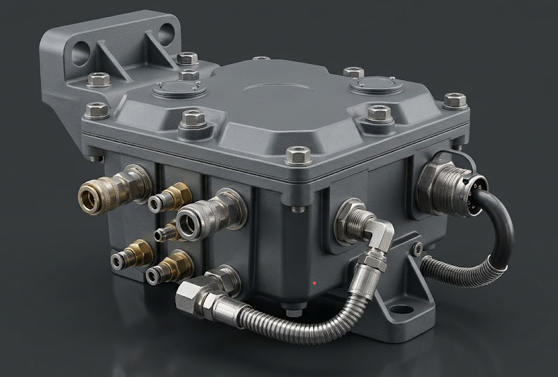
Rail operators spend a great deal of money on two things that are rarely said in the same sentence: wheelsets and traction energy. Both are strongly influenced by what happens in the few square centimetres where the wheel flange meets the rail head. Dry steel-on-steel contact in curves grinds flanges away, raises rolling resistance, produces the squeal that communities complain about, and eventually forces costly reprofiling. Automatic wheel flange lubrication addresses all four at once, and the component that decides whether the system actually works is the track lubrication controller.
What the controller has to do
The principle is simple to state and difficult to execute: deliver a small, repeatable quantity of lubricant to the flange at the right moment, no more and no less. Too much lubricant and adhesion suffers, contaminating the running surface and creating a braking hazard. Too little and nothing is achieved. Because the acceptable band is narrow, metering consistency — not flow capacity — is what separates a serious system from decorative hardware.
In a typical rail installation, the system is mounted on the locomotive and driven by compressed air, which most locomotives already generate. When the controller receives a start signal — from speed, distance, curve detection or operator input — compressed air is admitted, precisely metered lubricant is mixed with the air stream, and the mixture is sprayed through a nozzle onto the wheel flange. As the wheelset rotates, lubricant is transferred from wheel to wheel, so all wheelsets behind the application point are treated from a limited number of nozzles.
Why pneumatic actuation suits the application
Compressed air is clean, already available, needs no electrical motor at the nozzle where space is tight, and tolerates the vibration and temperature swings of underframe mounting. Air also atomises the lubricant, which is what allows genuinely small quantities to be distributed evenly rather than delivered as a slug. Against this, air quality must be managed: water and oil carry-over from the compressor contaminate the lubricant charge and clog nozzles, so filtration and drainage should be designed in from the beginning.
Design points engineers should raise early
l Trigger logic. Distance-based, time-based or curve-based activation each suit different operating patterns; the right choice depends on the route profile.
l Nozzle position and aiming. Small angular errors drastically reduce transfer efficiency, and any rubbing or stone strikes on curves must be considered.
l Lubricant behaviour. Viscosity changes with temperature, so winter and summer performance should be validated separately.
l Service access. Refill intervals, filter element replacement and nozzle cleaning must be possible within the available depot window.
l Diagnostics. Recording cycles and fault codes allows maintenance to be planned from condition rather than calendar.
The same discipline in stationary plant
The underlying requirement — deliver the right amount of lubricant to several points reliably and know when something has failed — is not unique to rail. An industrial control lubrication controller performs it for fixed installations: cement plant lines, presses, conveyors, large gearboxes and heavy process equipment. The control cabinet manages the lubrication points in sequence, monitors the supply, and detects lubrication oil pressure so that a blocked line or a failed pump raises an alarm instead of quietly destroying a bearing.
Because these installations differ greatly in point count, pump type, pressure range, ambient conditions and the host control system, the cabinet is usually built to order rather than selected from a catalogue. That custom engineering is where the value sits: deciding how many circuits are needed, how they are monitored, how the controller talks to the plant PLC, and how failures are annunciated.
Counting the return
The payback calculation is refreshingly direct. Extended wheel and rail life defers reprofiling and rail grinding. Lower rolling resistance reduces traction energy. Reduced noise improves community relations on urban sections. Fewer lubrication-related failures improves availability and lets workshops plan rather than react. Very often the dominant saving is the one that is hardest to forecast: the avoided unscheduled stop.
For operators evaluating a rail vehicle lubrication system, the practical advice is to instrument a pilot installation, agree the measurements before installation, and judge the controller on metering consistency over months rather than on promises made at tender stage.