
August 11, 2026
Complete Guide to Track Lubrication Controller: Intelligent Chip Control Logic, Pressure Feedback & Construction Machinery Chassis Lubrication Application
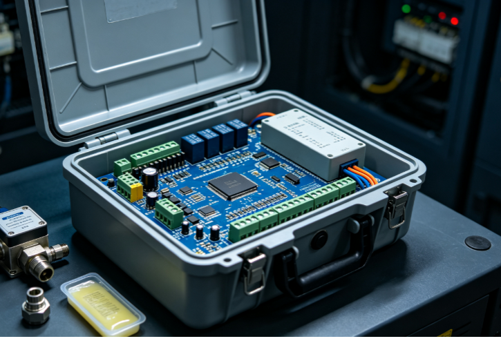
Table of Contents
1. Overview of Construction Machinery Chassis Track Lubrication Demand & Controller Core Value
2. Hardware Composition & Modular Architecture of Intelligent Track Lubrication Controller 2.1 Main Control Core: High-Stability Industrial Grade MCU Intelligent Chip 2.2 Multi-Channel Pressure Real-Time Feedback Detection Module 2.3 Drive Output Unit for Grease Pump & Solenoid Distributor Valve 2.4 Human-Machine Interaction & Vehicle CAN Bus Communication Interface 2.5 Power Supply Anti-Interference Protection Circuit for Construction Vehicle Harsh Environment
3. Intelligent Chip Core Control Logic & Full Working Cycle Algorithm 3.1 Timing Quantitative Lubrication Basic Control Program 3.2 Dynamic Adjustment Logic Based On Vehicle Working Condition Signal 3.3 Pressure Feedback Closed-Loop Self-Calibration & Fault Diagnosis Algorithm 3.4 Low Grease Level Automatic Reminder & Sleep Energy-Saving Logic 3.5 Overpressure, Blockage, Line Breakage Fault Interlock Protection Logic
4. Pressure Feedback System Working Principle & Calibration Standard 4.1 Pressure Sensor Installation Layout On Grease Pipeline 4.2 Real-Time Pressure Signal Acquisition & Chip Digital Filtering Processing 4.3 Standard Pressure Threshold Definition For Normal / Blocked / Leakage Status 4.4 Closed-Loop Correction: Automatically Adjust Pump Output According To Pipeline Pressure
5. Full Process Matching Application On Excavator, Bulldozer, Loader Chassis Track Lubrication 5.1 Excavator Track Link, Idler, Roller Lubrication Matching Scheme 5.2 Bulldozer Heavy-Duty Track Multi-Point Synchronized Grease Supply Control 5.3 Loader High-Frequency Shifting Chassis Variable Lubrication Interval Strategy 5.4 Installation Layout of Controller, Pressure Sensor, Grease Pump & Distributor Valve 5.5 Vehicle Cab Display Terminal Fault Prompt Logic
6. Seven Core Technical Advantages Of Chip-Controlled Pressure Feedback Track Lubrication Controller
7. Performance Comparison: Intelligent Closed-Loop Controller VS Traditional Simple Timing Lubrication Device
8. Common Chassis Lubrication System Faults & Controller Automatic Diagnosis Mechanism
9. Standard Factory Calibration, Aging Test & Vehicle Matching Debug Process
10. Industry FAQ For Construction Machinery Hydraulic & Electrical Component Manufacturers
1. Overview of Construction Machinery Chassis Track Lubrication Demand & Controller Core Value
Excavators, bulldozers, loaders and other construction machinery run in mud, sand, gravel and high-dust harsh working conditions all year round. The track assembly including track link, support roller, carrier roller, idler wheel and drive sprocket relies on continuous uniform grease lubrication to reduce metal friction wear, avoid track jamming and rust seizure. Traditional simple timing lubrication devices only execute fixed-time grease output without pipeline pressure monitoring feedback: insufficient grease supply leads to severe chassis abrasion; excessive grease causes waste and mud adhesion; pipeline blockage, grease leakage, empty grease tank faults cannot be automatically identified, resulting in frequent chassis maintenance and shortened track service life. The intelligent track lubrication controller takes industrial MCU chip as the core, built-in multi-channel pressure closed-loop feedback logic. It collects pipeline pressure data in real time, dynamically adjusts grease pump operating duration and grease output volume according to vehicle working condition signals, realizes quantitative, uniform, fault self-diagnosis intelligent lubrication of the whole chassis track, reduces chassis wear loss and post-sale maintenance cost by more than 40%.
2. Hardware Composition & Modular Architecture of Intelligent Track Lubrication Controller
2.1 Main Control Core: High-Stability Industrial Grade MCU Intelligent Chip
Adopt wide-temperature industrial control MCU chip (-40℃~+85℃ operating temperature), built-in 12-bit high-precision AD acquisition unit, 32K storage Flash for storing lubrication parameter curves and fault records. Support multi-task parallel operation: timing counting, pressure signal sampling, CAN signal parsing, drive output control and fault judgment run synchronously, with strong anti-electromagnetic interference performance adapted to construction vehicle high-current hydraulic environment.
2.2 Multi-Channel Pressure Real-Time Feedback Detection Module
Reserved 4–8 groups of analog pressure sensor signal input interfaces, matched with 0–10MPa high-reliability grease pressure sensors installed on main grease supply pipeline and each branch distributor outlet. The module carries signal amplification, noise filtering circuit, converts tiny pressure resistance variation into standard digital signal and transmits to MCU chip for real-time calculation.
2.3 Drive Output Unit for Grease Pump & Solenoid Distributor Valve
Independent high-current drive circuit, support direct driving DC grease pump (12V/24V construction vehicle standard voltage) and multi-channel solenoid divider valves. Each drive channel is equipped with overcurrent, short-circuit protection fuse; chip automatically cuts off output and records fault code when load short circuit occurs, avoiding circuit burnout.
2.4 Human-Machine Interaction & Vehicle CAN Bus Communication Interface
Two-way communication CAN bus interface conforming to SAE J1939 vehicle standard, can upload lubrication cycle, pipeline pressure, fault code, residual grease quantity data to vehicle central control display screen; support cab touch button parameter adjustment: modify lubrication interval, single grease output duration, upper/lower pressure alarm threshold without disassembling controller.
2.5 Power Supply Anti-Interference Protection Circuit for Construction Vehicle Harsh Environment
Built-in EMC anti-surge, anti-reverse connection, anti-transient high voltage protection circuit. Adapt to construction machinery generator unstable voltage fluctuation (9V~32V wide voltage input); filter circuit eliminates hydraulic pump, starter motor electromagnetic clutter interference to ensure chip continuous stable operation during vehicle vibration and startup impact.
3. Intelligent Chip Core Control Logic & Full Working Cycle Algorithm
3.1 Timing Quantitative Lubrication Basic Control Program
The chip sets independent timing registers for static parking lubrication and working state lubrication:
1. Working timing: Trigger lubrication cycle after the vehicle runs for a set time (adjustable 5–120min);
2. Parking timing: Short supplementary lubrication after engine shutdown to prevent track metal surface dry friction rust;
3. Quantitative control: Chip accurately controls grease pump power-on duration (0.5–10s stepless adjustment), realize fixed single grease output volume, avoid over-lubrication waste.
3.2 Dynamic Adjustment Logic Based On Vehicle Working Condition Signal
MCU parses vehicle CAN working condition data (engine load, walking motor running signal, forward/reverse track continuous operation time):
· Heavy load / long-time walking state: Automatically extend grease pump working time, increase single grease supply;
· Light load / intermittent short operation: Shorten lubrication interval and reduce grease output to save grease consumption;
· Static long parking mode: Enter low-frequency micro-lubrication cycle to avoid track rust.
3.3 Pressure Feedback Closed-Loop Self-Calibration & Fault Diagnosis Algorithm
This is the core unique logic of the intelligent controller:
1. After each lubrication pump starts, the chip continuously collects pipeline pressure signals within the grease supply period;
2. Compare real-time pressure with standard threshold range stored in Flash;
3. Automatically correct subsequent single grease output duration according to pressure feedback: low pressure indicates slight leakage, extend pump time to supplement grease; high pressure hints partial blockage, shorten pump time and trigger pre-alarm;
4. After lubrication ends, take the stable pressure value of the pipeline as the calibration benchmark for the next cycle, realize self-adaptive closed-loop correction without manual repeated debugging.
3.4 Low Grease Level Automatic Reminder & Sleep Energy-Saving Logic
Match liquid level sensor signal input of grease tank: When chip detects grease liquid level below reserve threshold, upload low-grease fault code to cab display and lock extended lubrication program to prevent air suction dry pumping damage to grease pump. When the vehicle engine is shut down for more than 30min, the MCU enters low-power sleep mode, only maintains pressure and liquid level signal real-time monitoring, greatly reducing standby power consumption of construction vehicle storage battery.
3.5 Overpressure, Blockage, Line Breakage Fault Interlock Protection Logic
Chip pre-stores three types of pressure fault judgment threshold:
1. Sustained pressure >7.5MPa: Pipeline complete blockage, immediately stop grease pump output, send blockage fault alarm;
2. Sustained pressure <1.0MPa: Main pipeline or branch pipe large leakage, trigger leakage fault prompt;
3. Pressure signal no change for long time: Pressure sensor line breakage, record circuit fault code. All fault states interlock protection: restrict long-time pump empty operation, protect grease pump and whole chassis lubrication pipeline system.
4. Pressure Feedback System Working Principle & Calibration Standard
4.1 Pressure Sensor Installation Layout On Grease Pipeline
· Main pipeline pressure sensor: Install at the outlet of the main grease pump, monitor total grease supply pressure of the whole vehicle chassis;
· Branch pressure sensors: Install at each outlet of the progressive distributor valve, separately detect grease supply pressure of left/right track independent lubrication circuits; Sensor mounting base adopts damping threaded joint to filter instantaneous pressure impact generated by grease pump startup, avoid signal distortion caused by mechanical vibration of construction machinery.
4.2 Real-Time Pressure Signal Acquisition & Chip Digital Filtering Processing
Pressure sensor outputs analog voltage signal changing with pipeline grease pressure; MCU AD unit samples pressure data 100 times per second, adopts moving average digital filtering algorithm to filter vibration clutter peak signal, extract stable effective pressure value, eliminate false alarm caused by vehicle bump and hydraulic impact.
4.3 Standard Pressure Threshold Definition For Normal / Blocked / Leakage Status
Take construction machinery chassis lithium base grease as calibration benchmark:
1. Normal lubrication working pressure: 2.0MPa ~ 6.0MPa, controller executes standard timing quantitative program;
2. Overpressure blockage pre-alarm threshold: 6.5MPa, cab display pre-alarm prompt to inspect pipeline distributor; complete blockage protection threshold: 7.5MPa, cut off pump drive output;
3. Leakage alarm threshold: 1.0MPa, judge pipeline breakage, joint loose grease leakage fault.
4.4 Closed-Loop Correction: Automatically Adjust Pump Output According To Pipeline Pressure
After completing one lubrication cycle, the chip records the average stable pressure of the pipeline:
· Average pressure 2.0~4.0MPa: Slightly insufficient grease supply, automatically increase single pump-on time by 15% in the next cycle;
· Average pressure 5.5~6.0MPa: Excessive grease supply, reduce pump working time by 10% to save grease;
· Pressure stays in standard 4.0~5.0MPa interval: Keep original lubrication parameter unchanged.
5. Full Process Matching Application On Excavator, Bulldozer, Loader Chassis Track Lubrication
5.1 Excavator Track Link, Idler, Roller Lubrication Matching Scheme
Small & medium excavators adopt single main pump + dual-channel progressive distributor valve, two groups of pressure sensors monitor left and right track branch pipelines separately. Controller combines excavator walking continuous operation signal to increase grease supply during long-distance transfer; short-distance swing operation reduces lubrication volume, effectively solve excavator track link pin dry wear problem in muddy working conditions.
5.2 Bulldozer Heavy-Duty Track Multi-Point Synchronized Grease Supply Control
Large bulldozer chassis has more lubrication points, adopt multi-outlet distributor with 6 groups of branch pressure feedback. The chip controls multi-way solenoid valves to supply grease to front idler, rear sprocket, upper carrier roller and lower support roller in batches. When bulldozer pushes heavy soil with heavy track load, the pressure feedback system automatically increases total grease output to avoid metal dry friction under heavy load.
5.3 Loader High-Frequency Shifting Chassis Variable Lubrication Interval Strategy
Loaders frequently forward and reverse, track impact load changes drastically. The controller chip parses walking gearbox shift signal, shortens lubrication cycle by 30% under frequent shifting working condition; static material waiting state extends lubrication interval, balance chassis wear and grease consumption cost.
5.4 Installation Layout of Controller, Pressure Sensor, Grease Pump & Distributor Valve
1. Lubrication controller: Install inside vehicle electrical control box, away from high-temperature engine exhaust area, reserved waterproof and shock absorption mounting support;
2. Grease pump & grease tank: Install at the side of chassis counterweight, convenient for manual grease filling;
3. Main pressure sensor: Mount on pump outlet straight pipe section, avoid elbow flow turbulence interference;
4. Branch pressure sensors: Install after each distributor outlet, convenient for quickly positioning single branch blockage fault.
5.5 Vehicle Cab Display Terminal Fault Prompt Logic
All pressure abnormal, low grease, circuit breakage fault codes are synchronously transmitted to cab liquid crystal display screen, display text prompt + fault light double alarm: distinguish main pipeline blockage, single branch leakage, low grease liquid level different fault types, maintenance personnel can quickly locate fault position without disassembling chassis pipeline.
6. Seven Core Technical Advantages Of Chip-Controlled Pressure Feedback Track Lubrication Controller
1. Closed-loop pressure feedback intelligent correction, realize self-adaptive quantitative grease supply, no insufficient lubrication or grease waste;
2. Industrial MCU chip multi-signal parallel processing, simultaneously support timing control, CAN working condition parsing and multi-channel pressure detection, high integration;
3. Full-automatic fault diagnosis of pipeline blockage, leakage, sensor line breakage and low grease, reduce chassis post-sale maintenance frequency;
4. Dynamic lubrication parameter adjustment linked with vehicle actual working load, targeted optimize track lubrication effect under different working conditions;
5. Wide-temperature, anti-EMC, anti-surge hardware circuit design, adapt to construction machinery high vibration, high dust, voltage fluctuation harsh environment;
6. CAN bus vehicle communication compatible with mainstream construction machinery whole vehicle control system, support cab one-key parameter setting;
7. Low-power sleep standby logic, reduce construction vehicle storage battery power consumption during long-time parking.
7. Performance Comparison: Intelligent Closed-Loop Controller VS Traditional Simple Timing Lubrication Device
Unified test condition: 20-ton excavator chassis track lubrication system, continuous 500h mud working condition test
表格
Test Index | Intelligent Chip Pressure Feedback Lubrication Controller | Traditional Fixed Timing Simple Lubricator | Construction Vehicle Application Impact |
Grease consumption per 500h | Save 32% grease consumption | Fixed excessive grease output, serious waste | Reduce vehicle daily operating material cost |
Track link pin average wear loss | Reduce 41% abrasion loss | Partial insufficient lubrication serious wear | Extend track assembly service life, cut replacement cost |
Pipeline blockage/leakage fault discovery | Real-time automatic alarm during first abnormal cycle | No feedback, fault found only after track seizure | Avoid sudden chassis failure construction shutdown loss |
Lubrication output adjustment mode | Pressure closed-loop self-adaptive dynamic correction | Fixed pump time, manual disassembly parameter adjustment | Reduce after-sale debugging labor cost |
Vehicle working condition linkage control | Automatically adjust grease supply according to load | Single fixed cycle regardless of heavy/light load | Poor lubrication matching under variable working condition |
Fault data recording function | Store 1000 groups of historical pressure fault records | No fault storage, unable to trace failure cause | Convenient manufacturer after-sales failure analysis |
Standby power consumption after engine shutdown | Sleep low power mode, 12mA standby current | Continuous full-power operation, high battery loss | Prevent long parking battery power shortage unable to start |
8. Common Chassis Lubrication System Faults & Controller Automatic Diagnosis Mechanism
1. Main grease pipeline complete blockage: Pipeline sustained overpressure >7.5MPa, chip stop pump output, pop up "main pipeline blockage" alarm on cab screen;
2. Single branch distributor outlet blockage: Corresponding branch pressure sensor overpressure, display independent branch fault code, quickly locate blocked lubrication point;
3. Pipeline joint loose grease leakage: Circulation average pressure persistently lower than 1.0MPa, trigger whole vehicle pipeline leakage alarm;
4. Grease tank liquid level insufficient: Liquid level sensor signal threshold triggered, low grease reminder, limit long-time high-load lubrication cycle;
5. Pressure sensor wire open circuit: Pressure signal maintains fixed value without fluctuation, chip record sensor circuit break fault;
6. Grease pump internal wear insufficient oil output: Each cycle pipeline average pressure gradually decreases year by year, controller pre-alarm to remind pump maintenance replacement.
9. Standard Factory Calibration, Aging Test & Vehicle Matching Debug Process
1. Chip parameter solidification calibration: Standard pressure threshold, lubrication timing range, pump output duration parameter write into MCU Flash before delivery;
2. Continuous power aging test: Controller power on for 72h continuous simulation pressure signal cycle test, screen chip signal acquisition and drive circuit unstable defective products;
3. Wide-temperature reliability test: −40℃~+85℃ temperature box cyclic test, verify chip pressure acquisition accuracy under extreme temperature;
4. Whole vehicle bench matching debugging: Connect grease pump, distributor, pressure sensor to simulate chassis pipeline pressure change, check closed-loop correction response speed;
5. Offline field vehicle loading calibration: After installation on excavator/bulldozer, adjust lubrication cycle and pressure alarm threshold according to customer working condition (mining/mud/road construction);
6. Fault function full inspection: Simulate blockage, leakage, line breakage and low grease four fault states one by one, verify alarm output and interlock protection function is effective.
10. Industry FAQ For Construction Machinery Hydraulic & Electrical Component Manufacturers
Q1: What core difference does pressure feedback closed-loop logic bring compared with fixed timing lubrication?
A1. Traditional timing lubrication only controls pump running time mechanically, cannot perceive actual grease filling state inside the pipeline: blockage causes overpressure damage to pump, leakage leads to chassis lack of oil wear. The MCU chip collects real-time pressure data after each lubrication, automatically increases or decreases grease output volume in the next cycle, realize self-adaptive quantitative lubrication, and synchronously judge various pipeline faults, which is the core difference of intelligent control.
Q2: Can this controller be compatible with 12V light load loader and 24V heavy bulldozer at the same time?
A2. Yes. The power supply circuit adopts 9–32V wide voltage anti-surge design, matched with 12V/24V general grease pump drive circuit; only need to switch the internal chip voltage parameter file during production without changing hardware structure, compatible with all mainstream tonnage construction machinery.
Q3: How many groups of pressure sensors can the controller access at most, suitable for multi-distributor multi-track heavy equipment?
A3. Standard model reserves 6 groups of analog pressure signal input ports, customized extended version supports up to 8 channels, can separately monitor the pressure of front and rear, left and right multiple independent lubrication circuits of large bulldozers and mining heavy load excavators, realize single branch independent fault positioning.
Q4: Does the CAN bus communication function support matching domestic new energy electric construction machinery?
A4. Fully compatible. The communication protocol follows SAE J1939 vehicle standard, can realize data interaction with traditional fuel vehicle whole vehicle controller and new energy electric drive main control unit simultaneously, upload lubrication system status to central control display, and receive whole vehicle working condition signal to adjust lubrication strategy.
Q5: Is the controller chip easy to be interfered by construction machinery hydraulic electromagnetic clutter? How to solve it?
A5. The whole machine is equipped with multi-layer EMC anti-interference design: power supply anti-surge circuit, signal input isolation filter, digital moving average filtering algorithm inside the MCU chip. A large number of loading verification shows that even under the environment of hydraulic pump, starter high-current electromagnetic interference, pressure signal acquisition has no false fluctuation and false alarm.